Fixed-Wing Trimming Guide
Trims are used to calibrate the control surfaces at trim conditions (relative airspeed, air density, angle of attack, aircraft configuration, etc.). A properly trimmed aircraft flying at trim conditions will keep its attitude without requiring any control inputs from the pilot or the stabilizing computer.
General aviation, commercial and large unmanned planes trim their control surfaces using trim tabs while small UAVs simply add an offset to the actuator of the control surface.
The Basic trimming section explains the purpose of each trim parameter and how to find the correct value. The Advanced Trimming section introduces parameters that can be set to automatically adjust the trims based on the measured airspeed and flap position.
Basic Trimming
There are several parameters an operator might want to use in order to properly trim a fixed-wing aircraft. An overview of those parameters and their use case is shown below:
- RCx_TRIM applies trim to the signal received from the RC transmitter. These parameters are set automatically during RC calibration.
- CA_SV_CSx_TRIM applies trim to a control surfaces channel. These are used to finely align the control surfaces to default angles before flying.
- FW_PSP_OFF applies an offset to the pitch setpoint. This is used to set the angle of attack at which your aircraft needs to fly at cruise speed.
- FW_AIRSPD_TRIM is used by the rate controllers to scale their output depending on the measured airspeed. See Airspeed Scaling for more details.
- TRIM_ROLL, TRIM_PITCH and TRIM_YAW apply trim to the control signals before mixing.
For example, if you have two servos for the elevator,
TRIM_PITCHapplies trim to both of them. These are used when your control surfaces are aligned but the aircraft pitches/rolls/yaws up/down/left/right during manual (not stabilized) flight or if the control signal has a constant offset during stabilized flight.
The correct order to set the above parameters is:
- Trim the servos by physically adjusting the linkages lengths if possible and fine tune by trimming the PWM channels (use
PWM_MAIN/AUX_TRIMx) on the bench to properly set the control surfaces to their theoretical position. - Fly in stabilized mode at cruise speed and set the pitch setpoint offset (
FW_PSP_OFF) to desired angle of attack. The required angle of attack at cruise speed corresponds to the pitch angle that the airplane needs to fly at in order to keep constant altitude during wing-leveled flight. If you are using an airspeed sensor, also set the correct cruise airspeed (FW_AIRSPD_TRIM). - Look at the actuator controls in the log file (upload it to Flight Review and check the Actuator Controls plot for example) and set the pitch trim (
TRIM_PITCH). Set that value to the average offset of the pitch signal during wing-leveled flight.
Step 3 can be performed before step 2 if you don't want to have to look at the log, or if you feel comfortable flying in manual mode.
You can then trim your remote (with the trim switches) and report the values to TRIM_PITCH (and remove the trims from your transmitter) or update TRIM_PITCH directly during flight via telemetry and QGC.
Advanced Trimming
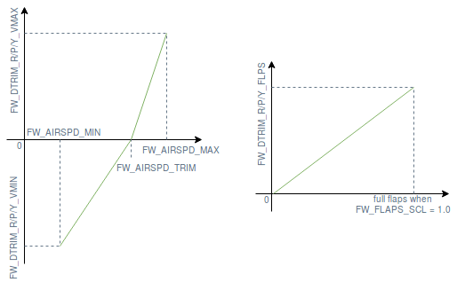
Given that the downward pitch moment induced by an asymmetric airfoil increases with airspeed and when the flaps are deployed, the aircraft needs to be re-trimmed according to the current measured airspeed and flaps position. For this purpose, a bilinear curve function of airspeed and a pitch trim increment function of the flaps state (see figure below) can be defined using the following parameters:
- FW_DTRIM_[R/P/Y]_[VMIN/VMAX] are the roll/pitch/yaw trim value added to
TRIM_ROLL/PITCH/YAWat min/max airspeed (defined by FW_AIRSPD_MIN and FW_AIRSPD_MAX). - CA_SV_CSx_FLAP and CA_SV_CSx_SPOIL are the trimming values that are applied to these control surfaces if the flaps or the spoilers are fully deployed, respectively.

A perfectly symmetrical airframe would only require pitch trim increments, but since a real airframe is never perfectly symmetrical, roll and yaw trims increments are also sometimes required.