
NP-RID-Sender Remote ID Transmitter
Overview
The NP-RID-Sender is a broadcast UAV remote identification transmitter from NextPilot. It meets the requirements of the GB 46750-2025 standard and can broadcast UAV operating status over WiFi and Bluetooth to satisfy UAV flight supervision requirements. It currently supports MAVLink and DroneCAN connections and works with ArduPilot, PX4 and other autopilots. Custom development is available if you need to support other autopilots or protocols.
Purchase link: https://item.taobao.com/item.htm?id=1074097497449&mi_id=0000KHD5urOB5ulWhlh0CZLkO54UwXlaqMXVS7sOhyvD7lY
Video tutorial: nextpilot RID transmitter module (bilibili)
Product Functions
- Communicates with the autopilot to obtain UAV operating status;
- Broadcasts WiFi beacon frames;
- Broadcasts over Bluetooth 5;
- Views UAV status from a web page;
- Provides a WiFi telemetry link;
- Provides a virtual RID simulation function;
- Supports parameter configuration — connect the device with a serial terminal and set all parameters quickly using parameter commands;
- Supports OTA upgrade.
Specifications
- Supported main control chips: ESP32-S3 / ESP32-C3;
- Interfaces: 2 serial ports (autopilot serial port and debug serial port), 1 USB, 1 CAN;
- Supported input protocols: MAVLink, DroneCAN;
- Supported transmit signal types: WiFi broadcast beacon frames, Bluetooth 5;
- Transmit power: 20 dBm;
- Transmit protocol: GB46750.
Hardware
The following hardware variants are currently supported:
- NP-RID-Sender-S3-GH
- NP-RID-Sender-C3-PinMini
| Appearance | Hardware name | Description |
|---|---|---|
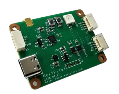 | NP-RID-Sender-S3-GH | Main chip: ESP32-S3 All functions available, can be mounted directly on the UAV External antenna Debug serial port is UART2 |
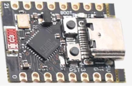 | NP-RID-Sender-C3-PinMini | Main chip: ESP32-C3 No external antenna, no CAN support, generally used for testing. Debug serial port is UART0 |
Interface Description
NP-RID-Sender-S3-GH
The external interfaces of each hardware variant are described below:
| Interface | Pinout | Remarks |
|---|---|---|
| USB | USB, Type-C | For developers: firmware flashing and debugging |
| UART1 | RX: GPIO17 TX: GPIO18 | Autopilot serial port Default baud rate 115200 Connector marked J6 |
| UART2 | RX: GPIO44 TX: GPIO43 | Debug serial port Used for debugging and parameter configuration with a USB-to-TTL module Default baud rate 115200 Connector marked J4 |
| CAN | RX: GPIO38 TX: GPIO47 | Connect directly to the autopilot CAN bus Connector marked J5 |
NP-RID-Sender-C3-PinMini
The external interfaces of each hardware variant are described below:
| Interface | Pinout | Remarks |
|---|---|---|
| USB | USB, Type-C | For developers: firmware flashing and debugging |
| UART0 | RX: GPIO20 TX: GPIO21 | Debug serial port Used for debugging and parameter configuration Default baud rate 115200 |
| UART1 | RX: GPIO2 TX: GPIO3 | Autopilot serial port Default baud rate 115200 |
| CAN | RX: GPIO4 TX: GPIO5 | Requires an external CAN transceiver |
Quick Start (PX4 + QGC)
Connecting the Autopilot First
The connection is described here using the NP-RID-Sender-S3-GH and a CUAV V7+ autopilot as an example.
Connecting Over a Serial Port
Use the included autopilot serial cable (4-pin to 6-pin) to connect device UART1 to autopilot TELEM1 or TELEM2.
TIP
First set the baud rate of autopilot TELEM1 or TELEM2 to 115200 in the QGC ground station. For example, the TELEM1 baud rate is set by modifying the parameter SER_TEL1_BAUD. Reboot after setting the baud rate.
The wiring is as follows:
| Autopilot TELEM2 | RID device UART1 |
|---|---|
| 5V | 5V |
| GND | GND |
| TX | RX |
| RX | TX |
The connection is shown below:

INFO
TELEM1 is connected here and its default baud rate is 115200. If you connect a different autopilot serial port, set the RID module serial baud rate accordingly. Connecting other autopilots is much the same: just make sure the autopilot supplies power and that the serial TX/RX lines are crossed!
Connecting Over CAN
Use the included autopilot CAN cable (4-pin to 4-pin) to connect device CAN to autopilot CAN1.
QGC Ground Station Configuration
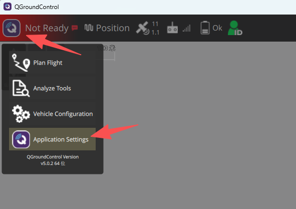
Opening the Settings Screen
Click the main menu button in the top-left corner, then select Application Settings.
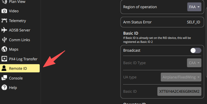
Then select RemoteID in the list on the left of the software configuration screen.
Setting the Product Unique ID
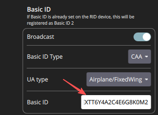
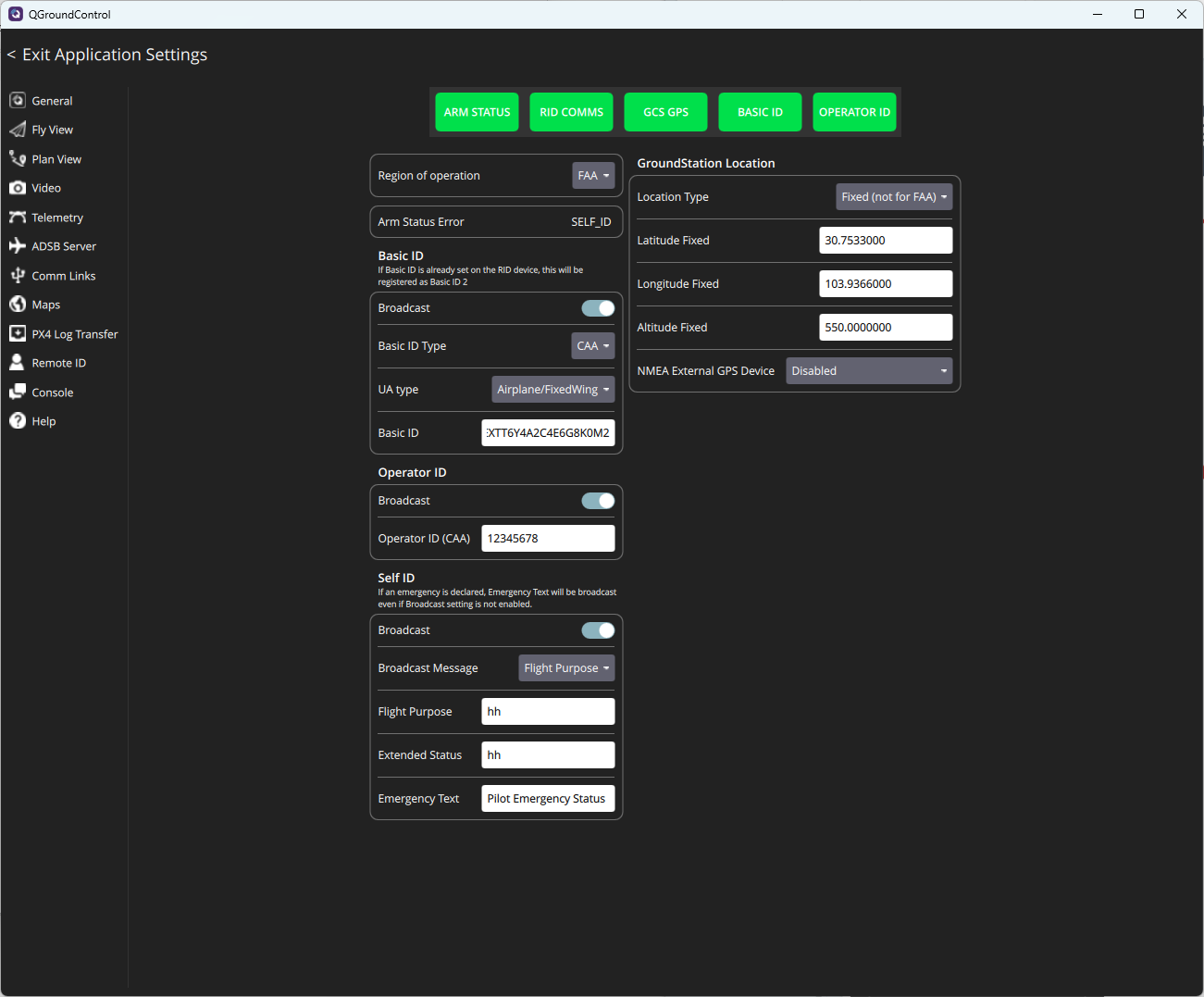
Turn on the Broadcast slider in the BasicID section. Enter a 20-character product unique ID.
Setting Real-Name Registration
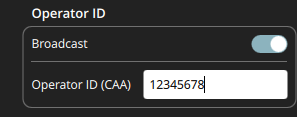
Turn on the Broadcast slider in the OperatorID section. Enter 8 characters of real-name registration information, i.e. the last 8 digits of the operator's ID number.
Setting the Operation Category
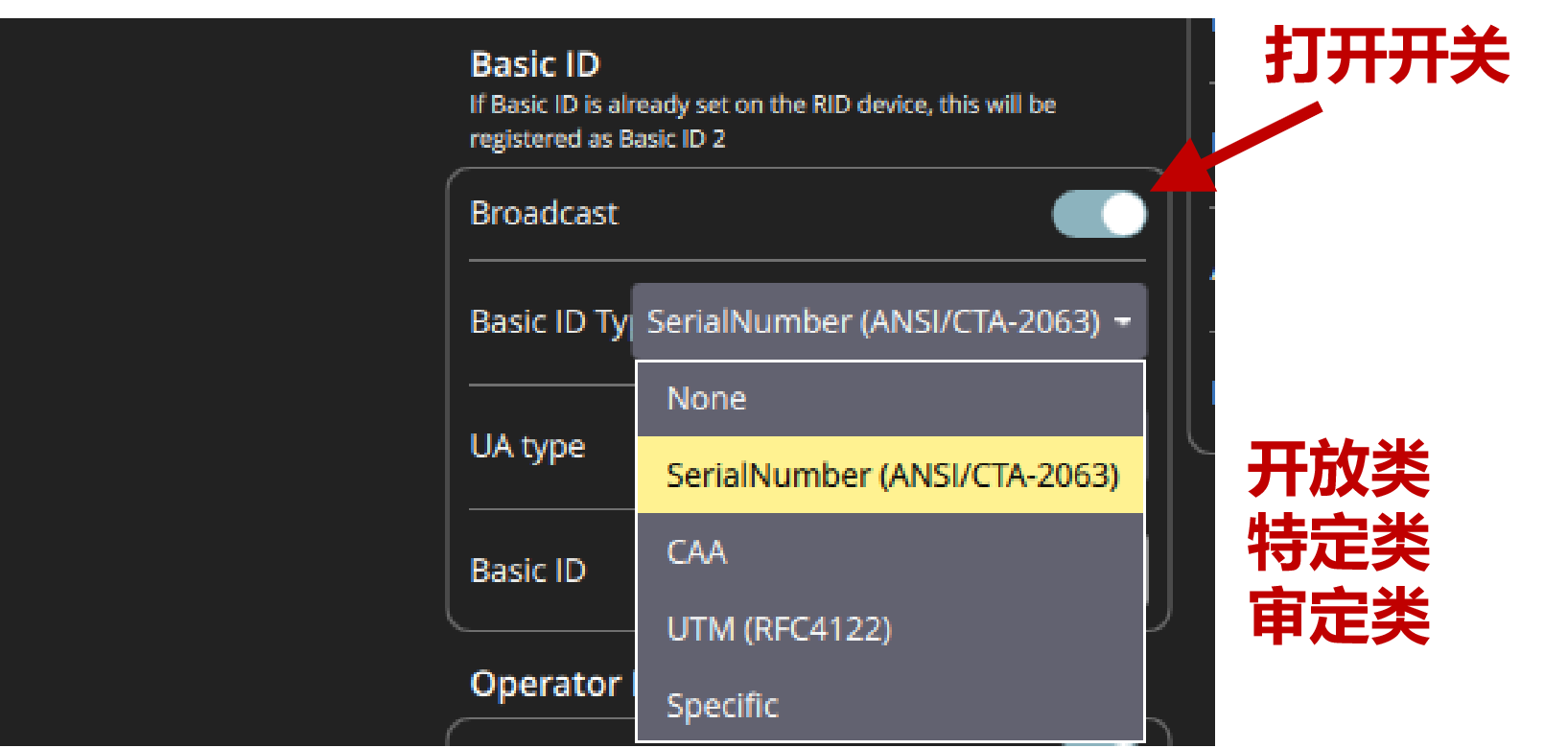
Since QGC does not include the Chinese GB46750 standard, the existing types must be mapped. The mapping is:
- Select SerialNumber to set the development category;
- Select CAA to set the specific category;
- Select UTM to set the certified category.
Setting the UAV Classification
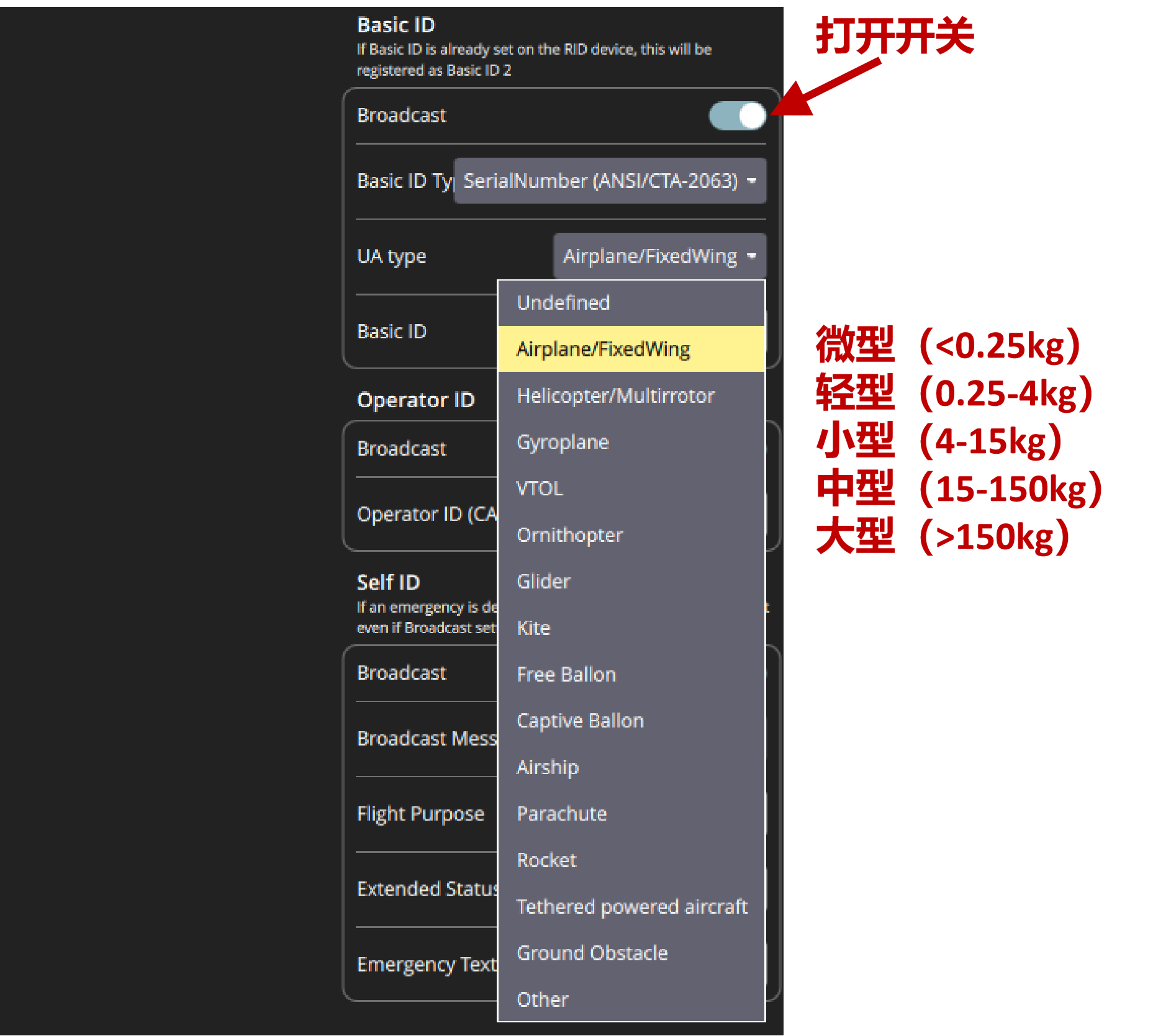
The correspondence between the existing names and the names in the GB46750 standard is shown below:
Setting the Pilot Station Position
Selecting Fixed is recommended, then enter the ground station latitude, longitude and altitude.
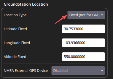
If anything other than Fixed is selected, the RID automatically uses the autopilot takeoff point position.
Final Configuration
Viewing Status on the Web Page
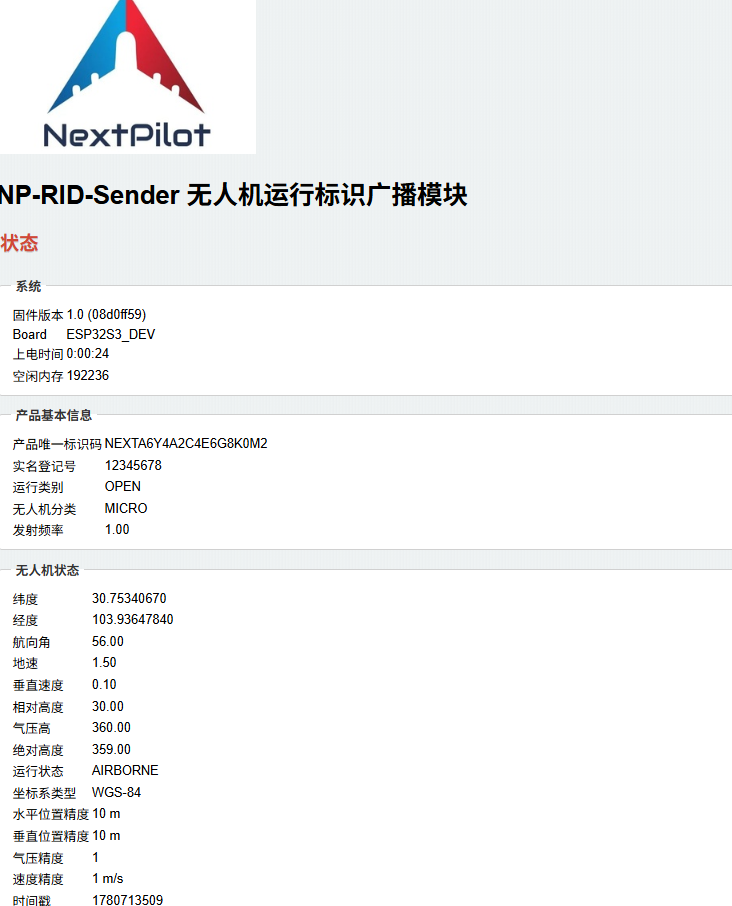
After powering on the UAV, place it in an open outdoor area to acquire satellite positioning.
After the RID powers on it automatically starts a WiFi hotspot (hotspot name NP-RID-xxxxxx, password nextpilot). Connect your laptop to the hotspot, open a browser and go to http://192.168.4.1 to see the device operating status.
Verifying RID Reception
Reception can be verified with a mobile app or with test RID receiving equipment.
Receiving device: NP-RID-Receiver
Mobile app: Download the SouSouFly app
Parameter Configuration
Parameters can be set flexibly over the debug serial port to control the device operating logic — setting the serial baud rate, starting the WiFi hotspot, enabling print output — which greatly simplifies testing during use.
Connecting the Device
Use the debug cable (4-pin to 4-pin DuPont cable) to connect the RID device to the included USB-to-TTL serial module, then plug the module into the computer. The connection principle is shown below:
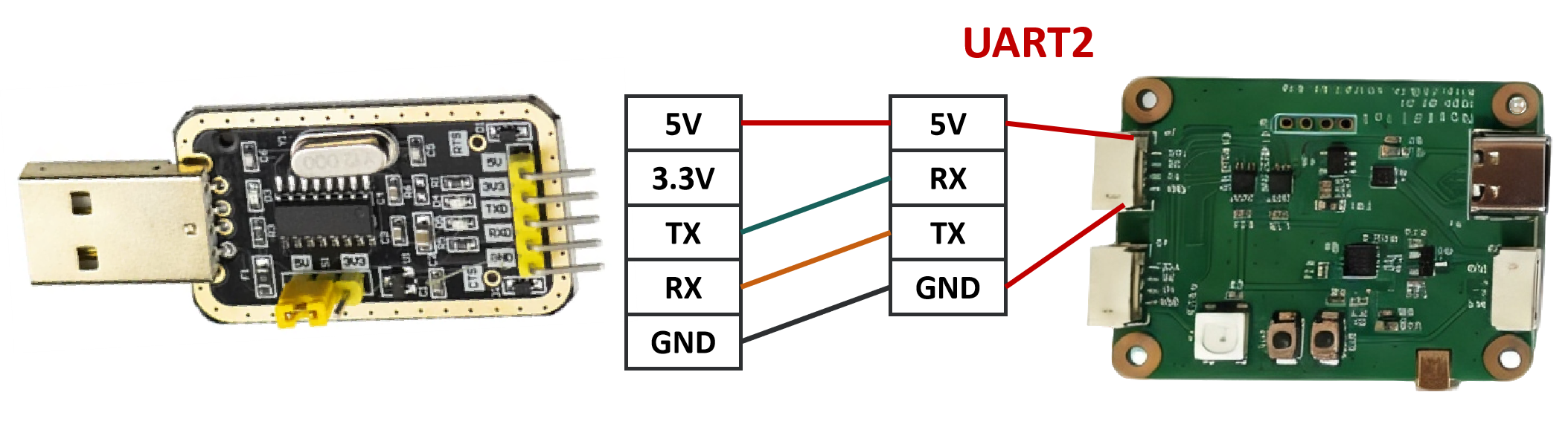
The NP-RID-Sender-S3-GH board is used as an example here. If you use a different board, find the debug serial port for that board in Interface Description, connect it to the USB-to-TTL module, and then plug the module into the computer.
Sending Commands
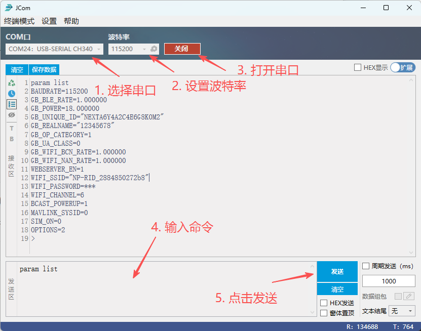
Open the JCom serial terminal on the computer (download: JCom | Professional real-time curve serial assistant - Jooiee), set the port number (auto-detected) and baud rate (115200), then click Open. Enter the command followed by a carriage return, then click the Send button.
Common Commands
The relevant parameter commands are listed below:
| Operation | Command | Example |
|---|---|---|
| List all parameters | param list | List all parameters: param list |
| Reset parameters to defaults | param reset | Reset to defaults: param reset |
| Read a specific parameter | param get [name] | Read the data output baud rate: param get CFG_BAUD |
| Set a parameter | param set [name] [value] |
Command examples
- Set serial port 1 baud rate:
param set BAUDRATE 115200 - Set the UAV unique ID:
param set GB_UNIQUE_ID prodYYMMDD0123456789 - Set real-name registration:
param set GB_REALNAME 08082330 - Set the UAV to the small class:
param set GB_UA_CLASS 1 - Restore defaults:
param reset
TIP
- The unique product ID must be exactly 20 characters, otherwise it cannot be set.
- The real-name registration number must be exactly 8 numeric characters, otherwise it cannot be set. :::
Parameter Reference
Common parameters are described below:
| Parameter | Description | Remarks |
|---|---|---|
| WIFI_SSID | WiFi hotspot name | NP-RID-xxxxxx |
| WIFI_PASSWORD | WiFi password | Hidden, default nextpilot |
| GB_UNIQUE_ID | UAV unique identifier | Requires UOM certification |
| BAUDRATE | Serial port 1 baud rate | Default 115200 |
| GB_WIFI_NAN_RATE | WiFi-NAN broadcast rate | Default 1 time / second |
| GB_WIFI_BCN_RATE | WiFi-Beacon broadcast rate | Default 1 time / second |
| WIFI_CHANNEL | WiFi broadcast channel | Default 6 |
| WIFI_POWER | WiFi power | Default -20 dBm |
| GB_BLE_RATE | Bluetooth 5 broadcast rate | Default 1 time / second |
| GB_REALNAME | Real-name registration, last 8 ID digits | |
| GB_OP_CATEGORY | Operation category | 0: undeclared; 1: open; 2: specific; 3: certified. See GB46750-2025 for details |
| GB_UA_CLASS | UAV classification | 0: micro (<0.25 kg) 1: light (0.25-4 kg) 2: small (4-15 kg) 3: medium (15-150 kg) 4: large (>150 kg) See GB46750-2025 |
| WEBSERVER_EN | Enable / disable the web server | Default 1, enabled |
| SIM_ON | Enable / disable RID simulation | Default 0, disabled |
| OPTIONS | UAV basic information configuration option | 0: use parameter settings; 2: use ground station configuration (default) |
Advanced Functions
Basic Information Configuration
Setting the unique product ID
param set GB_UNIQUE_ID NEXTpil0tA2C4E6G8K0M2The product ID must be a 20-character combination of digits and letters registered with UOM.
Setting the real-name registration ID
param set GB_REALNAME 12340206The real-name registration ID must consist of 8 digits!
Setting the UAV classification
param set GB_UA_CLASS 1The numbers correspond to the following UAV classes:
- 0: micro, < 0.25 kg (MICRO)
- 1: light, 0.25-4 kg (LIGHT)
- 2: small, 4-15 kg (SMALL)
- 3: medium, 15-150 kg (MEDIUM)
- 4: large, > 150 kg (LARGE)
Setting the operation category
param set GB_OP_CATEGORY 1The numbers correspond to the following operation categories:
- 1: OPEN
- 2: SPECIFIC
- 3: CERTIFIED
Reboot the RID device after configuration.
RID Simulation
If you need to test without an autopilot connected, the product can simulate a RID. Configuration steps:
- Connect the serial terminal
- Send the configuration command:
param set SIM_ON 1 - Reboot the device
To disable RID simulation, simply enter param set SIM_ON 0 and reboot the device.
Time Synchronization
Time synchronization is required in the following situations:
- After connecting the UAV (the RID module uses the UAV system time by default) but the UAV system time is invalid;
- After enabling RID simulation, when time accuracy matters.
Configuration steps:
Connect the debug serial port to the computer and open the serial terminal;
Set a time one minute ahead, and when that moment arrives send Beijing time in the following format:
bashparam set GB_UTC8_TIME 2026-09-21T10:30:00Note that the date string must not contain spaces, hence the letter
Tas separator.You can also set the Unix time directly (in seconds):
bashparam set GB_UTC_TIME 1789833600
WiFi Telemetry
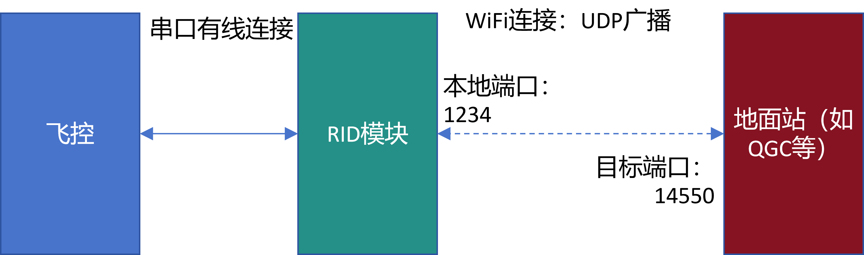
After power-on the RID module broadcasts autopilot data received over the serial port to all computers connected to its hotspot, using UDP broadcast on the local network segment. The RID module thus acts as a WiFi telemetry link, transparently forwarding autopilot data to the ground station.
TIP
Only autopilot serial port data is forwarded; CAN data is not forwarded.
Procedure
- Connect the autopilot TELEM serial port to the RID data serial port and confirm the baud rates match;
- Open the QGC ground station on the laptop;
- Connect the laptop to the RID module hotspot; QGC automatically establishes communication with the autopilot.
Using the RID module WiFi telemetry provides stable data communication within roughly 200 meters — low cost, simple and convenient, well suited to everyday debugging.
OTA Upgrade
Firmware Download
| Board | Current firmware version | Download |
|---|---|---|
| NP-RID-Sender-S3-GH | V1.2 | OTA app firmware |
| NP-RID-Sender-C3-PinMini | V1.0 | OTA app firmware |
Updating Firmware
Connect to the RID device hotspot, open the page http://192.168.4.1, click "Choose file", select the downloaded firmware and click the Update button. The device reboots automatically after the upgrade.

FAQ
- After completing all configuration in the ground station, the error "Arm uninitilized" still appears. Check whether RID simulation is enabled and disable it with
param set SIM_ON 0;
Changelog
v1.0
Initial version, completing the basic RID functions.
v1.2
Fixed protocol assignment errors, optimized WiFi broadcast, and added time synchronization.