
Device Installation
Coordinate System Definition
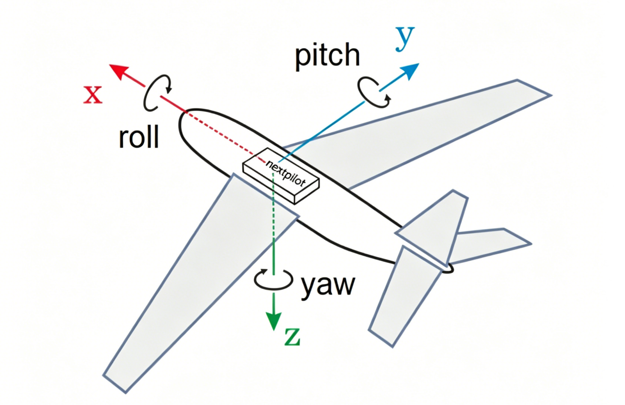
Body coordinate system: the origin is at the UAV center of gravity, the X axis points forward (nose direction), the Y axis points to the right of the fuselage, and the Z axis points downward. As shown below:
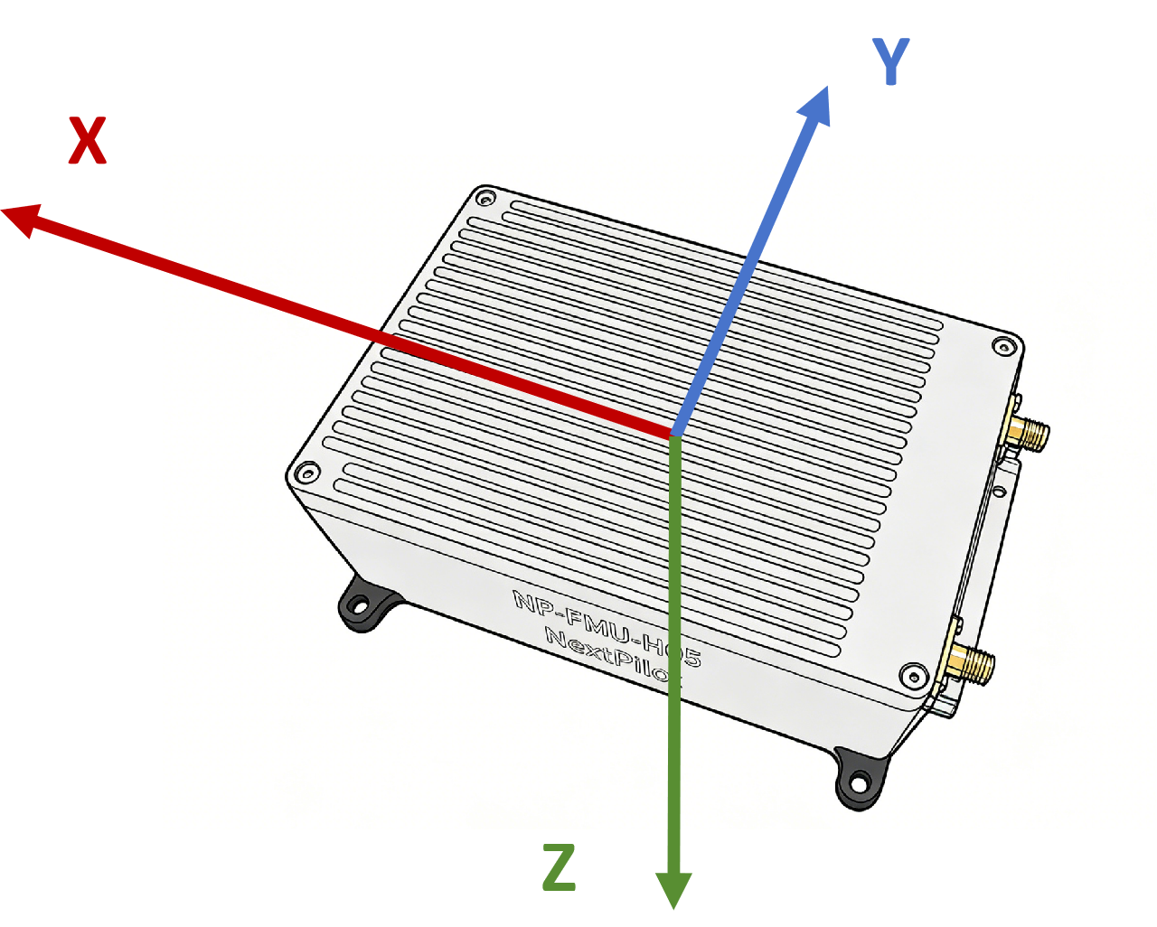
Autopilot coordinate system: the origin is at the center of the autopilot, the connector side is the rear, the front side of the autopilot is the X axis, the right side is the Y axis, and downward is the Z axis. The coordinate axes are printed on the autopilot housing, as shown below:
Flight Control Computer
Where installation conditions permit, the autopilot should be mounted at the UAV center of gravity so that the autopilot coordinate system coincides with the UAV coordinate system.
If it cannot be mounted at the center of gravity, you need to set the mounting position offset of the autopilot on the airframe platform. Mounting position definition: the coordinates of the autopilot origin in the body coordinate system. The corresponding parameters are EKF2_IMU_POS_X, EKF2_IMU_POS_Y and EKF2_IMU_POS_Z.
If the coordinate systems cannot coincide, adjust the autopilot mounting angle according to the actual installation conditions. Mounting angle definition: with the body coordinate system as reference, the rotation angle of the autopilot coordinate system relative to the body coordinate system. The corresponding parameter is SENS_BOARD_ROT.
For several typical installations, the corresponding rotation angles and mounting positions are configured as follows:
| Installation example | Rotation angle | Mounting position |
|---|---|---|
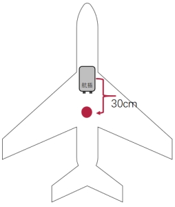 | No rotation, ROTATION_NONE | EKF2_IMU_POS_X=0.3 EKF2_IMU_POS_Y=0 EKF2_IMU_POS_Z=0 |
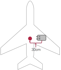 | Rotate 90° clockwise, ROTATION_YAW_90 | EKF2_IMU_POS_X=0 EKF2_IMU_POS_Y=0.3 EKF2_IMU_POS_Z=0 |
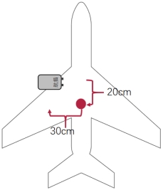 | Rotate 90° counter-clockwise, ROTATION_YAW_270 | EKF2_IMU_POS_X=0.2 EKF2_IMU_POS_Y=-0.3 EKF2_IMU_POS_Z=0 |
Airborne GNSS Antennas
By default the primary satellite antenna is at the rear and the secondary antenna at the front, so the direction from the primary to the secondary antenna matches the nose direction. If not, you need to set a rotation angle. Rotation angle definition: the angle between the vector from the primary antenna to the secondary antenna and the X axis of the body coordinate system (currently only rotation in the horizontal plane is supported), positive clockwise. The corresponding parameter is GPS_YAW_OFFSET.
For connecting the autopilot primary and secondary antennas, refer to Electrical Interfaces in the product description.
By default the primary satellite antenna is installed at the UAV center of gravity. If not, you need to set the primary antenna position; the corresponding parameters are EKF2_GPS_POS_X, EKF2_GPS_POS_Y and EKF2_GPS_POS_Z. Mounting position definition: the coordinates of the primary antenna in the body coordinate system.
For several typical installations, the corresponding rotation angles and mounting positions are configured as follows:
| Installation example | Rotation angle | Mounting position |
|---|---|---|
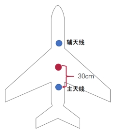 | GPS_YAW_OFFSET=0 | EKF2_GPS_POS_X=-0.3 EKF2_GPS_POS_Y=0.0 EKF2_GPS_POS_Z=0.0 |
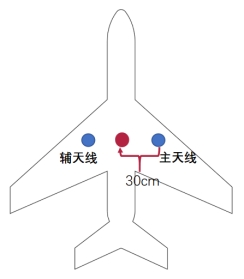 | GPS_YAW_OFFSET=270 | EKF2_GPS_POS_X=0.0 EKF2_GPS_POS_Y=0.3 EKF2_GPS_POS_Z=0.0 |
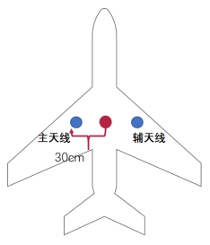 | GPS_YAW_OFFSET=90 | EKF2_GPS_POS_X=0.0 EKF2_GPS_POS_Y=-0.3 EKF2_GPS_POS_Z=0.0 |
Air Data Computer
The airspeed sensor has no special mounting position requirement. It can be bonded or fixed to the airframe using its screw holes. Then connect the dynamic and static pressure ports of the airspeed sensor to the pitot tube. Make sure the airspeed hose is not folded or blocked, which would make the differential pressure measurement inaccurate.
Ground RTK Base Station
Used as a General RTK Base Station
Place the base station statically on the ground and connect the primary antenna.
Used in Moving Platform Takeoff and Landing Operations
For takeoff and landing on moving platforms (such as vehicles or vessels), the autopilot needs the following two pieces of information to land the UAV in the designated area of the moving platform:
- The relative position of the landing point and the primary antenna;
- The relative angle between the primary / secondary antennas and the moving platform.
With the primary antenna at the origin, the front of the moving platform as the positive X axis, the right side as the positive Y axis and downward as the positive Z axis, a coordinate system is established. The coordinates of the landing point in this coordinate system are its position relative to the primary antenna; the corresponding autopilot parameters are RMB_DX, RMB_DY and RMB_DZ.
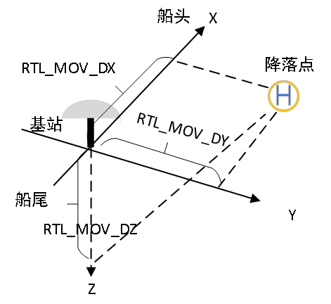
The line from the primary antenna to the secondary antenna forms a straight line; the angle between this line and the X axis is the relative angle, and the corresponding autopilot parameter is RMB_OFFSET_HDG.
The correspondence between several typical dual-antenna orientations and the parameter is:
Secondary antenna in front, primary antenna behind:
RMB_OFFSET_HDG=0;Secondary antenna on the right, primary antenna on the left:
RMB_OFFSET_HDG=90;Secondary antenna on the left, primary antenna on the right:
RMB_OFFSET_HDG=270.