Basic Setup
Airframe Setup
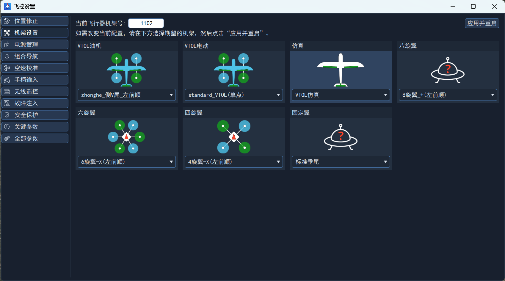
To better support and adapt to different UAV platforms, the autopilot provides airframe parameters. The core differences between airframes lie in the number, position and layout of the propulsion units or control surfaces — for example a vertical tail differs greatly from a V-tail, and rotor rotation directions differ.
In addition, default values are set for flight parameters that differ significantly between airframes, such as PID inner loop gains, loiter radius and forward transition timeout.
Select the airframe in Autopilot Setup -> Airframe Setup; a reboot is required for the change to take effect.
Remote Controller Setup
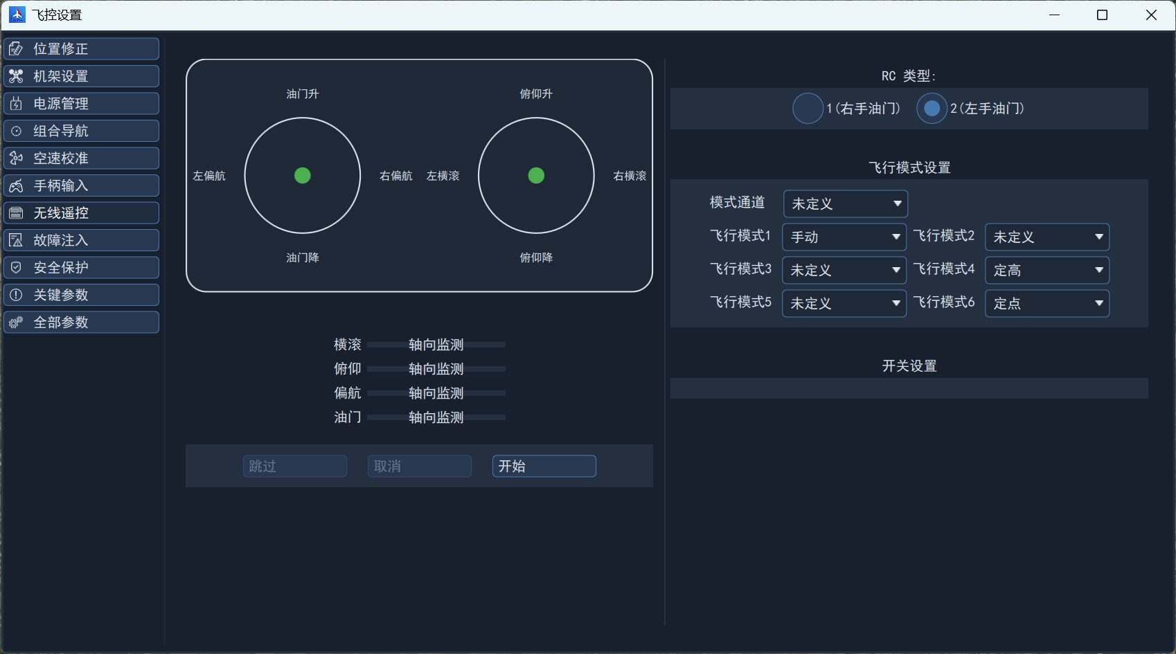
Configure the remote controller in Autopilot Setup -> Radio Control.
Mode Setup
Select a channel bound to a three-position switch and map it to the mode channel; channel 5 is used by default.
By default flight mode 1 is Manual, flight mode 4 is Altitude and flight mode 6 is Position.
Calibration
Check the RC mode according to the remote controller type, click the "Start" button and follow the prompts to calibrate.
Motor Setup
Calibration
Complete calibration first according to the motor product documentation!
Confirming Motor Rotation Direction
According to the airframe setup, confirm the motor rotation direction in the ground station.
Control Surface Reversal
Control surface reversal applies only to VTOL and fixed-wing aircraft; multirotor vehicles ignore it.
Switch to fixed-wing flight mode, unlock with the remote controller and operate the control surfaces. If a surface is reversed, set the corresponding surface using the parameters below. If the original value is 0 change it to 1; if it is 1 change it to 0.
| Parameter | Pin | Device (determined by actual vehicle) |
|---|---|---|
| PWM_AUX_REV1 | FCS_CH9 | Left aileron |
| PWM_AUX_REV2 | FCS_CH10 | Right aileron |
| PWM_AUX_REV3 | FCS_CH11 | Elevator / left V-tail |
| PWM_AUX_REV4 | FCS_CH12 | Rudder / right V-tail |
Control Surface Trim
Control surface trim applies only to VTOL and fixed-wing aircraft; multirotor vehicles ignore it.
Switch to fixed-wing flight mode, unlock with the remote controller and operate the control surfaces. If a surface is not centered, adjust it using the parameters below.
| Parameter | Pin | Device (determined by actual vehicle) |
|---|---|---|
| PWM_AUX_TRIM1 | FCS_CH9 | Left aileron |
| PWM_AUX_TRIM2 | FCS_CH10 | Right aileron |
| PWM_AUX_TRIM3 | FCS_CH11 | Elevator / left V-tail |
| PWM_AUX_TRIM4 | FCS_CH12 | Rudder / right V-tail |
Note that the parameter range is -0.2~0.2, i.e. at most 20% adjustment. If a surface deviates too far, mechanical adjustment is required.
Calibrating Battery Voltage
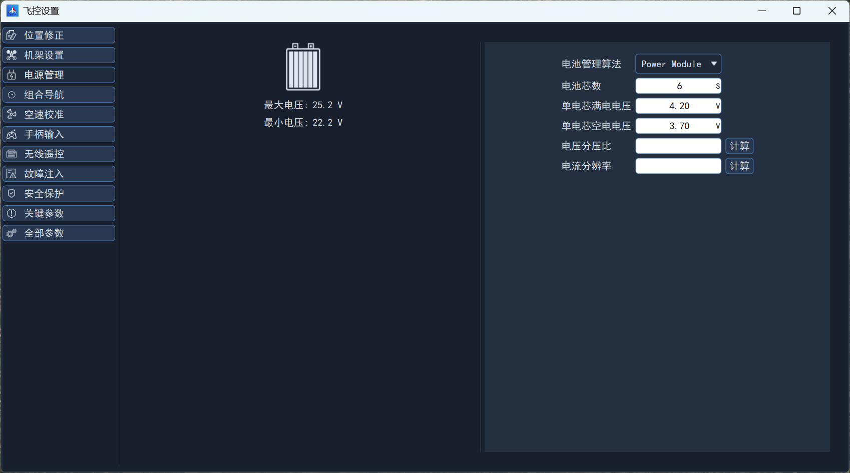
First measure the traction battery voltage with a multimeter, then apply traction power, go to Autopilot Setup -> Power Management, enter the cell count, click the voltage divider ratio calculation button, enter the measured voltage and click Calculate.