Mission Planning
Click the "Mission Planning" button in the General section of the left sidebar of the ground station, or click the main menu in the top-left corner and select Mission Planning, to open the mission planning screen.
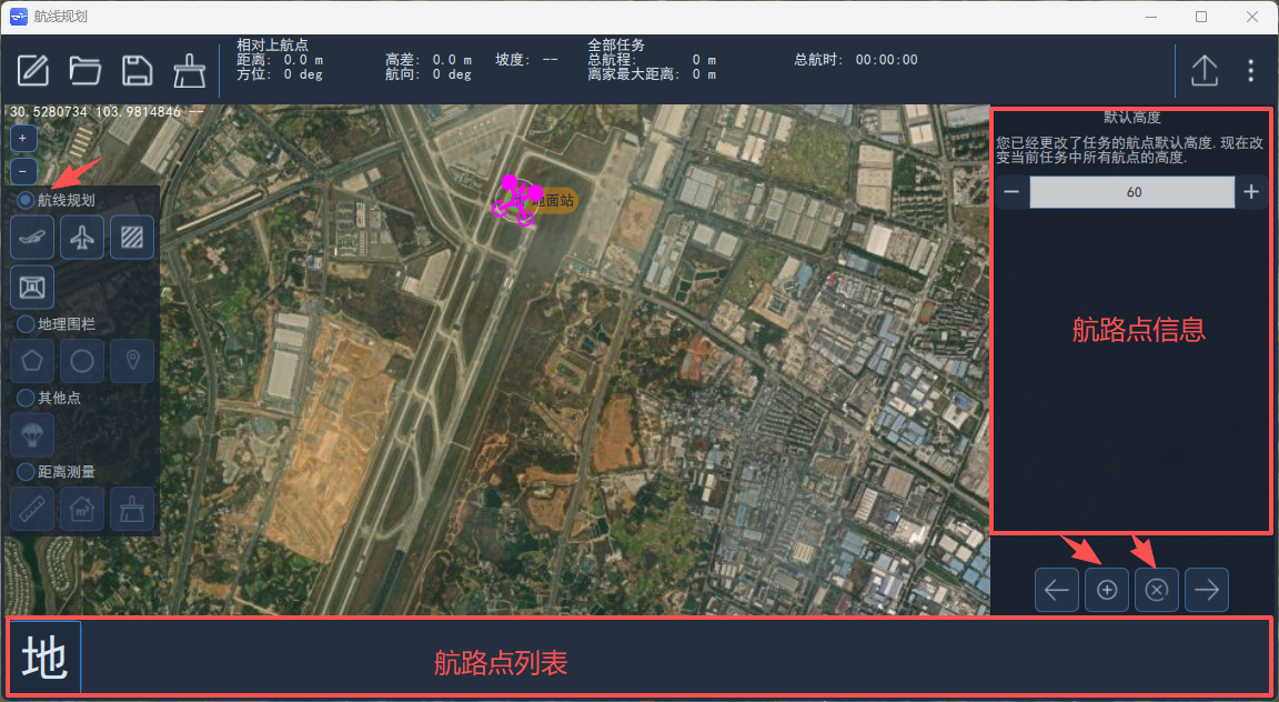
The mission planning screen has a toolbar and status bar at the top, planning function selection on the left, waypoint information on the right, and the planned waypoint list at the bottom.
Drawing a Flight Path
Adding a Vertical Takeoff Waypoint
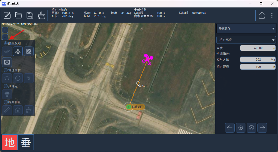
For VTOL aircraft, the first waypoint of the path must be a VTOL vertical takeoff waypoint when performing autonomous mission flight.
When drawing a path, first click the "Takeoff" icon under mission planning on the left, then left-click near the UAV departure direction to add a VTOL vertical takeoff waypoint.
Adding Waypoints
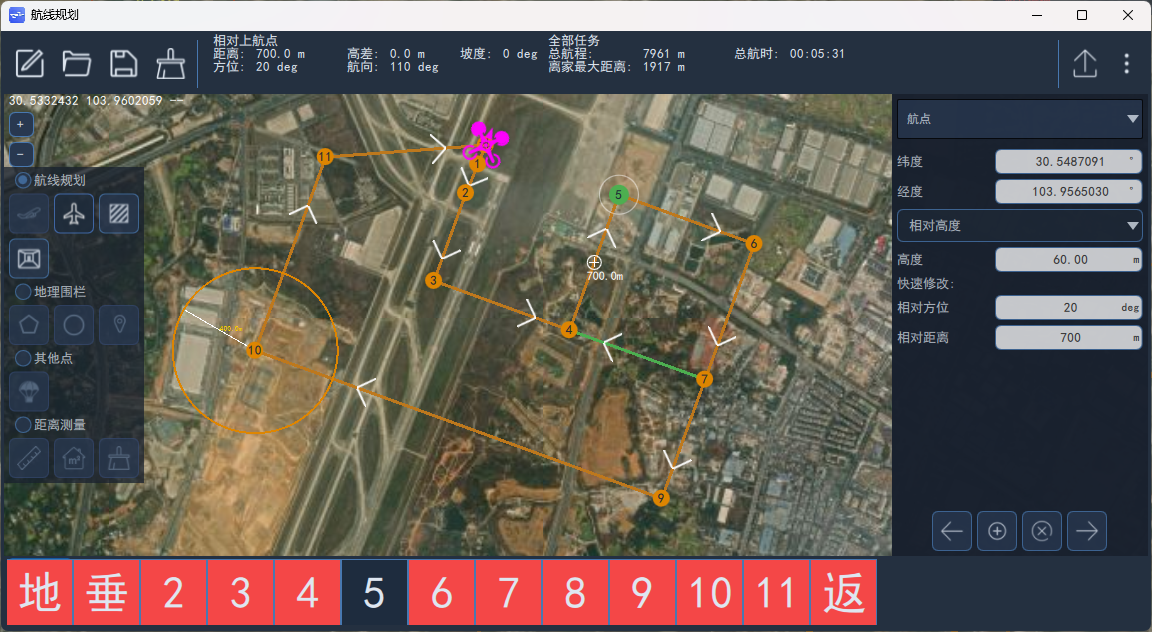
Then select Waypoint and left-click on the map to add a waypoint.
Changing the Waypoint Type
More than ten waypoint types are currently supported. To change the waypoint type, select the waypoint and choose from the waypoint type drop-down list on the right, as shown below:
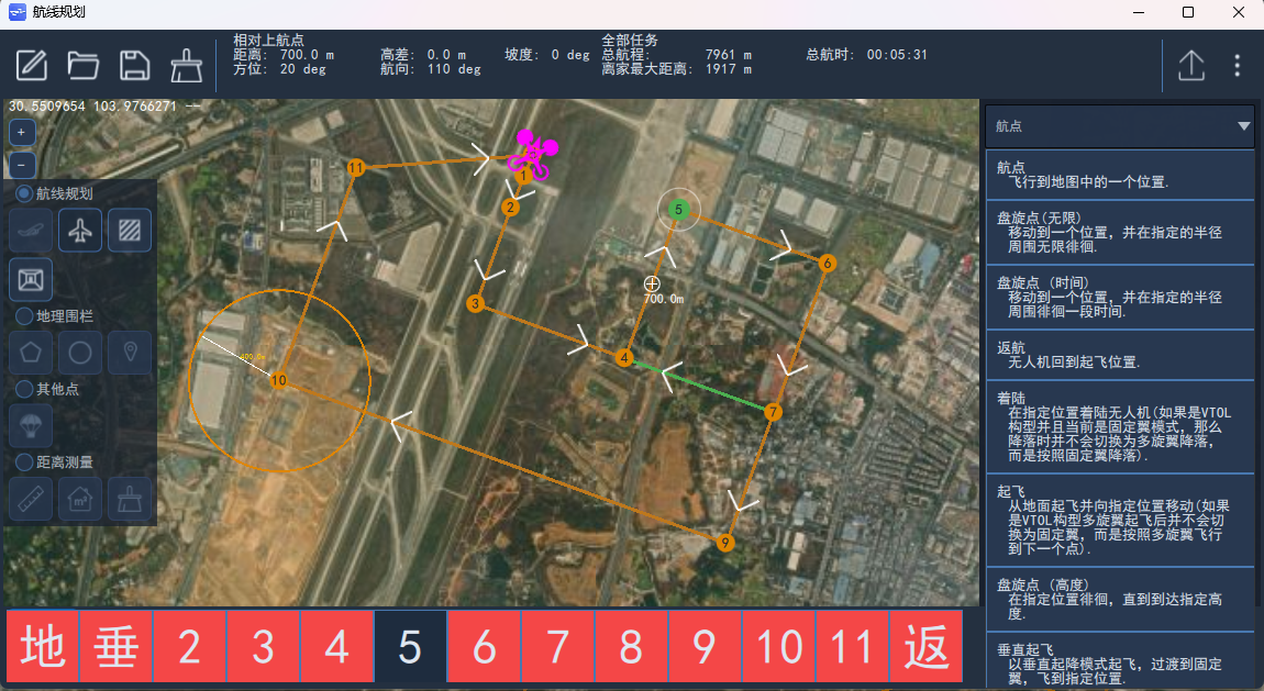
See Common Waypoint Types for details on each waypoint type.
Modifying Waypoint Attributes
Attributes differ depending on the waypoint type. Select a waypoint to view or modify its attributes on the right. You can also set the position of the next point using the relative bearing and relative distance fields under Quick Edit.
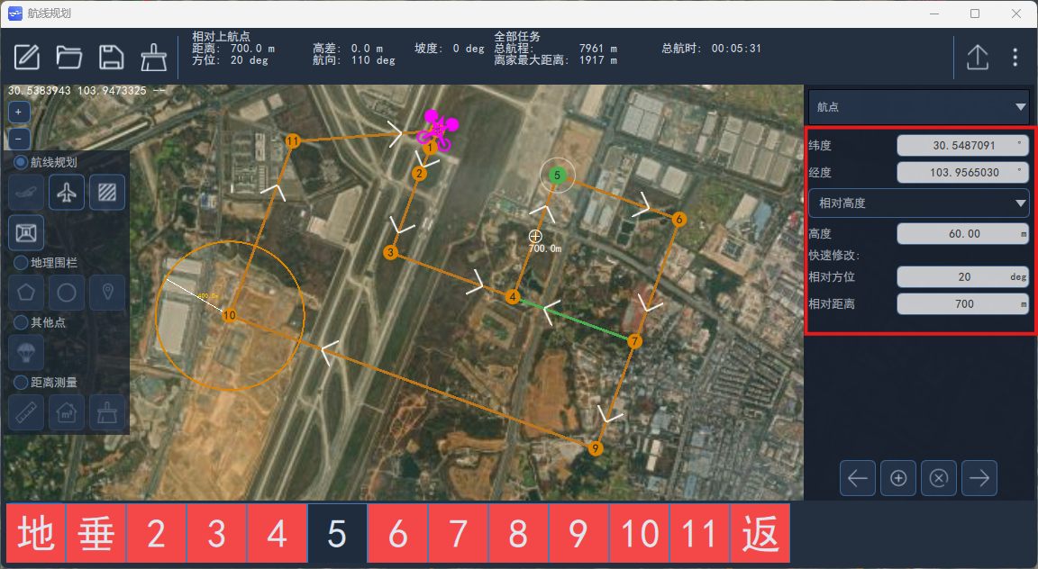
Common Waypoint Types
VTOL Takeoff
When a VTOL fixed-wing UAV flies in Mission mode, this waypoint must be selected as the first waypoint, otherwise the UAV cannot automatically switch to fixed-wing flight mode. After setting this point, the VTOL UAV takes off vertically in multirotor mode; once it reaches the specified altitude it automatically rotates its heading to align with the point, then starts the rear pusher / front puller propulsion and begins the multirotor-to-fixed-wing transition.
Waypoint
An ordinary waypoint controls the horizontal position and altitude of the UAV. The UAV is considered to have reached the waypoint when both the horizontal position and the altitude reach the set values. When flying in fixed-wing mode, if the horizontal position is reached but the altitude is not, the UAV circles to reach the set altitude.
Return To Launch
The return-to-launch waypoint is a command waypoint (command waypoints do not control UAV position or altitude; they act as control commands sent automatically during flight). When the UAV reaches the waypoint before the return-to-launch waypoint, it automatically switches to return mode.
VTOL Transition and Land / Land
For VTOL fixed-wing UAVs the VTOL landing waypoint and the land waypoint share the same control logic: when the target point is this waypoint, the UAV begins the multirotor transition once its distance to the waypoint is less than the back-transition distance.
Loiter
This is an unlimited loiter point. You can set the loiter altitude, loiter radius and loiter direction (clockwise or counter-clockwise). When the UAV distance to the loiter point is greater than the sum of the loiter radius and the turn lead distance (NAV_ACC_RAD), the UAV flies straight from its current position toward the loiter point with the altitude command set to the configured loiter altitude; when the UAV altitude reaches the configured loiter altitude and the horizontal distance is less than the sum of the loiter radius and the turn lead distance, loiter control begins.
Loiter (time)
Loiter by time: the UAV exits the loiter and continues the mission when the loiter time elapses. This waypoint allows setting the loiter altitude, loiter time and loiter radius. A loiter setting greater than 0 means clockwise, less than 0 means counter-clockwise.
When the UAV distance to the loiter point is greater than the sum of the loiter radius and the turn lead distance, the UAV flies straight from its current position toward the loiter point with the altitude command set to the configured loiter altitude; when the UAV altitude reaches the configured altitude and the horizontal distance is less than the sum of the loiter radius and the turn lead distance, loiter control begins.
When exiting the loiter you can configure heading hold and tangent exit, as shown below. With heading exit configured, the UAV exits the loiter once its heading aligns with the next waypoint after the loiter time elapses; with tangent exit configured, the UAV first flies to the tangent point and then to the next waypoint. If neither heading hold nor tangent exit is configured, the UAV flies directly to the next waypoint after the configured loiter time.
Loiter (altitude)
Loiter until the specified altitude is reached; the UAV exits the loiter and continues the mission when the loiter altitude is reached. You can set the loiter altitude and loiter radius: a loiter setting greater than 0 means clockwise, less than 0 means counter-clockwise.
When the UAV distance to the loiter point is greater than the sum of the loiter radius and the turn lead distance, the UAV flies toward the loiter point along the path at its current altitude; when the horizontal distance to the loiter (altitude) waypoint is less than the sum of the loiter radius and the turn lead distance, loiter control begins.
Heading hold and tangent exit can be selected when exiting the loiter.
Jump to Item
Jump is a command waypoint; you can set the target waypoint number and the number of jumps. When the UAV reaches the waypoint before this one, the target waypoint is automatically set to the configured jump waypoint number; once the jump count is reached, no further jumps are performed.
Change Speed
The speed waypoint is a command waypoint that changes the UAV flight speed; you can set the UAV flight speed or throttle. When the UAV reaches the waypoint before this one, it flies according to the configured speed or throttle value.
Land Start
The land start waypoint is a command waypoint and requires no parameters. When the return type RTL_TYPE is set to 1 and the path contains a VTOL landing waypoint or a land waypoint, the UAV first flies straight to the waypoint after the land start waypoint during return, and then returns along the path according to the configured return route.
Geofence Setup
On the mission planning screen, check "Geofence" to draw polygon and circular fence areas on the map.
Click the "Polygon" icon, then left-click anywhere to draw a polygon fence. A quadrilateral is created by default. Hold the left button and drag the white dot to move the whole shape or individual vertices; click the "+" on an edge to add a new vertex. The latitude and longitude of each vertex are shown on the right and can be edited.
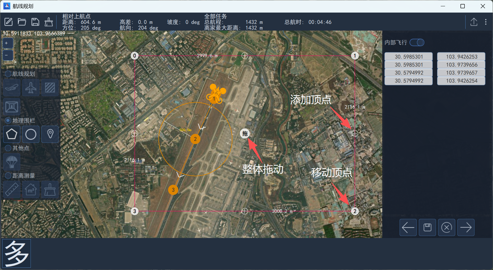
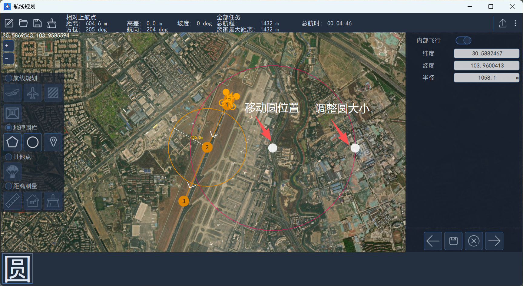
Click the "Circle" icon, then left-click anywhere to draw a circular fence. Hold the left button and drag the white dot to move and resize it. The center coordinates and radius are shown on the right and can be edited.