NP-FCC-H05 Navigation Flight Control Computer
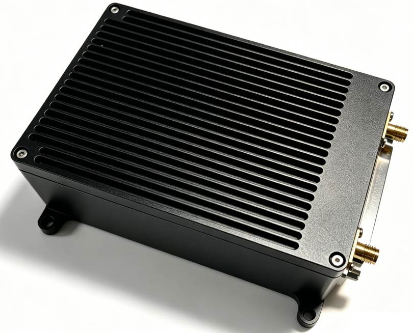
The NP-FCC-H05 is a high-performance, industrial-grade, integrated navigation and flight control product developed by the NextPilot team. It carries a high-performance, dual-redundant, internally damped inertial measurement unit (IMU), featuring high reliability, good stability and strong vibration resistance. It adopts self-developed navigation algorithms and loss-of-control protection strategies, delivering high positioning accuracy and strong anti-interference capability. It integrates powerful functions including moving-platform takeoff and landing, visual navigation and swarm formation flight, and provides an external flight control interface for secondary development to meet application development needs in various scenarios. The product applies to 10 kg~300 kg class UAV platforms of all types, including multirotor, fixed-wing, VTOL and tilt-rotor aircraft. Paired with a professional ground control station, it provides powerful flight functions and safe flight assurance.
Product Features
- Dual main processors, with flight control and navigation separated architecturally
- Built-in high-performance IMU, installable without extra damping
- Built-in high-performance navigation board
- Moving platform support
- Compliant with relevant GJB standards
Main Functions
The main functions of the navigation flight control computer are:
- Supports multiple vehicle types, including multirotor, fixed-wing and VTOL;
- Provides manual, altitude hold, position hold, acro, hover, mission, external control, autonomous takeoff and landing, return-to-launch and other flight modes;
- Provides emergency protection logic including data link loss protection, satellite signal loss protection, engine failure protection, low voltage warning and protection;
- Supports remote takeoff and landing;
- Provides geofence functionality;
- Supports hardware-in-the-loop and software-in-the-loop simulation;
- Supports multi-vehicle control;
- Supports multi-level formation;
- Broadly supports satellite navigation boards, including Novatel (OEM718D), Unicore (UM482, UM982) and others;
- Carries a high-precision industrial-grade IMU, requiring no external damping;
- Supports firmware upgrade over a serial port;
- Supports log recording and replay (PX4 log format);
- Supports software version query.
Specifications
Main Performance
The performance indicators of the navigation flight control computer are as follows:
- Supply voltage: DC 9~36 V;
- Power consumption: < 12 W;
- Startup time: no more than 40 s;
- Altitude control accuracy: < 1 m;
- Serial ports: 8 channels;
- PWM channels: 16;
- DO: 4 channels;
- ADC inputs: 4 channels;
- Gyroscope: measurement range ±400 °/s, gyro bias 20 °/h (1σ);
- Accelerometer: measurement range ±10 g, accelerometer bias 1 mg;
- Operating temperature: -40 °C ~ 75 °C;
- Storage temperature: -45 °C ~ 80 °C;
- High and low temperature operation, vibration, shock and electromagnetic compatibility comply with GJB requirements.
Dimensions and Weight
- Dimensions: ≤ 112 mm × 72 mm × 42 mm (L × W × H);
- Weight: 400 g;
- Mounting hole diameter 4 mm, spacing 107 mm × 87 mm.
Electrical Interfaces
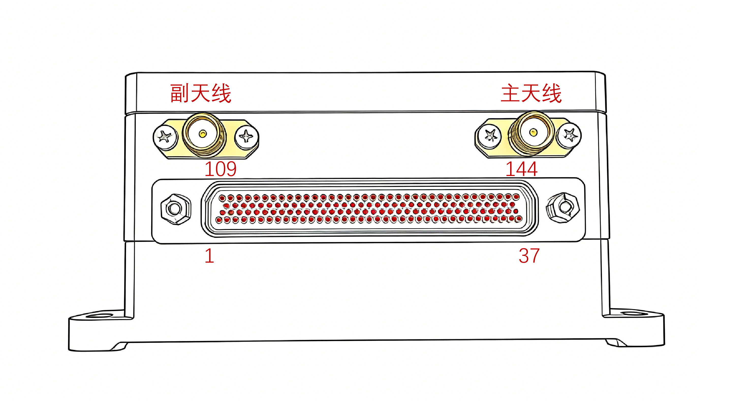
The flight controller provides two SMA connectors for dual antenna connection: the right one is the main antenna connector and the left one is the auxiliary antenna connector. An aviation connector, model J30J-144ZKW-J, is provided; the interface layout is shown below.
Pin Definition
The flight controller connector model is J30J-144ZKW-J; the pin definitions are as follows:
| No. | Pin | Signal | Description | External device (reference) |
|---|---|---|---|---|
| 1 | 2 | Power-VCC | Power input positive (DC 9~36 V) | |
| 2 | 3 | Power-VCC | ||
| 3 | 4 | Power-VCC | ||
| 4 | 38 | Power-GND | Power input negative (DC 9~36 V) | |
| 5 | 39 | Power-GND | ||
| 6 | 40 | Power-GND | ||
| 7 | 1 | EARTH | Chassis ground | |
| 8 | 74 | BATT1_VOL | Voltage sensing | Traction battery VCC pin |
| 9 | 75 | BATT1_CUR | Current sensing | |
| 10 | 76 | BATT1_GND | ADC1 ground | |
| 11 | 109 | ADC1_SPARE_1 | ADC input | |
| 12 | 110 | ADC1_SPARE_2 | ADC input | |
| 13 | 111 | ADC_GND | ADC2 ground | |
| 14 | 5 | FCS_DO1 | FCS board - DO1 | Integrated starter/generator, engine start switch |
| 15 | 6 | FCS_DO2 | FCS board - DO2 | Integrated starter/generator, generation control |
| 16 | 7 | FCS_DO3 | FCS board - DO3 | Integrated starter/generator, fuel pump switch |
| 17 | 8 | FCS_DO4 | FCS board - DO4 | Payload power control switch |
| 18 | 14 | DO_GND | GND2 | |
| 19 | 41 | FCS_ETH_RXN | FCS board Ethernet (currently unused) | Airborne network device |
| 20 | 42 | FCS_ETH_RXP | FCS board Ethernet (currently unused) | |
| 21 | 43 | FCS_ETH_TXN | FCS board Ethernet (currently unused) | |
| 22 | 44 | FCS_ETH_TXP | FCS board Ethernet (currently unused) | |
| 23 | 45 | GND2 | GND2 | |
| 24 | 51 | FCS_CH1 | PWM output CH1 | VTOL (front-right motor), multirotor (motor 1) |
| 25 | 52 | FCS_CH2 | PWM output CH2 | VTOL (rear-left motor), multirotor (motor 2) |
| 26 | 53 | FCS_CH3 | PWM output CH3 | VTOL (front-left motor), multirotor (motor 3) |
| 27 | 54 | FCS_CH4 | PWM output CH4 | VTOL (rear-right motor), multirotor (motor 4) |
| 28 | 55 | FCS_CH5 | PWM output CH5 | VTOL (front puller motor), multirotor (motor 5) |
| 29 | 56 | FCS_CH6 | PWM output CH6 | Multirotor (motor 6) |
| 30 | 57 | FCS_CH7 | PWM output CH7 | |
| 31 | 58 | FCS_CH8 | PWM output CH8 | |
| 32 | 15 | FCS_CH_GND1 | GND2 | |
| 33 | 16 | FCS_CH_GND2 | GND2 | |
| 34 | 17 | FCS_CH_GND3 | GND2 | |
| 35 | 18 | FCS_CH_GND4 | GND2 | |
| 36 | 87 | FCS_CH9 | PWM output CH9 | VTOL (left aileron servo) |
| 37 | 88 | FCS_CH10 | PWM output CH10 | VTOL (right aileron servo) |
| 38 | 89 | FCS_CH11 | PWM output CH11 | VTOL (elevator / left V-tail servo) |
| 39 | 90 | FCS_CH12 | PWM output CH12 | VTOL (rudder / right V-tail servo) |
| 40 | 91 | FCS_CH13 | PWM output CH13 | |
| 41 | 92 | FCS_CH14 | PWM output CH14 | |
| 42 | 93 | FCS_CH15 | PWM output CH15 | |
| 43 | 94 | FCS_CH16 | PWM output CH16 | VTOL (engine throttle) |
| 44 | 19 | FCS_CH_GND5 | GND2 | |
| 45 | 20 | FCS_CH_GND6 | GND2 | |
| 46 | 21 | FCS_CH_GND7 | GND2 | |
| 47 | 22 | FCS_CH_GND8 | GND2 | |
| 48 | 83 | RC_5V_OUT | Receiver 5 V supply | FUTABA receiver |
| 49 | 85 | RC_SBUS_IN | FCS serial port 8, SBUS input | FUTABA receiver |
| 50 | 84 | RC_SBUS_OUT | FCS serial port 8, SBUS output | |
| 51 | 82 | RC_GND | GND2 | |
| 52 | 47 | SAFETY_5V_OUT | 5V_ISO | Safety switch supply pin |
| 53 | 48 | SAFETY_SW_LED | Breathing LED pin | |
| 54 | 49 | SAFETY_SWITCH | Safety switch button pin | |
| 55 | 50 | BUZZER | External buzzer | |
| 56 | 46 | SAFETY_GND | GND2 | |
| 57 | 118 | I2C1_5V_OUT | 5V_ISO | |
| 58 | 119 | FCS_IIC_SDA | ||
| 59 | 120 | FCS_IIC_SCL | ||
| 60 | 86 | FCS_IIC_GND | GND2 | |
| 61 | 121 | INS_IIC_SDA | ||
| 62 | 122 | INS_IIC_SCK | ||
| 63 | 95 | INS_IIC_GND | GND2 | |
| 64 | 139 | FCS_CAN1_H | FCS_CAN1 | |
| 65 | 140 | FCS_CAN1_L | ||
| 66 | 141 | INS_CAN1_H | INS_CAN1 | |
| 67 | 142 | INS_CAN1_L | ||
| 68 | 101 | FCS_RS232_RX1 | FCS board serial port 5 (RS232) | Engine |
| 69 | 102 | FCS_RS232_TX1 | ||
| 70 | 103 | FCS_RS232_GND | ||
| 71 | 66 | FCS_RS232_RX2 | FCS board serial port 6 (RS232) | Gimbal |
| 72 | 67 | FCS_RS232_TX2 | ||
| 73 | 68 | FCS_RS232_GND | ||
| 74 | 117 | FCS_RS232_RX3 | FCS board serial port 7 (RS232) | |
| 75 | 116 | FCS_RS232_TX3 | ||
| 76 | 81 | FCS_RS232_GND | ||
| 77 | 123 | FCS_RS422_A1 | FCS board serial port 1 (RS422) | Primary data link |
| 78 | 124 | FCS_RS422_B1 | ||
| 79 | 125 | FCS_RS422_Y1 | ||
| 80 | 126 | FCS_RS422_Z1 | ||
| 81 | 127 | FCS_RS422_A2 | FCS board serial port 2 (RS422) | Secondary data link |
| 82 | 128 | FCS_RS422_B2 | ||
| 83 | 129 | FCS_RS422_Y2 | ||
| 84 | 130 | FCS_RS422_Z2 | ||
| 85 | 105 | FCS_CAN2_H | FCS board CAN2 | |
| 86 | 106 | FCS_CAN2_L | ||
| 87 | 104 | FCS_CAN2_GND | ||
| 88 | 70 | INS_RS232_RX1 | INS board serial port 7 | |
| 89 | 71 | INS_RS232_TX1 | ||
| 90 | 69 | INS_RS232_GND2 | ||
| 91 | 131 | FCS_RS422_A3 | FCS board serial port 3 (RS422) | Airborne computer for external control |
| 92 | 132 | FCS_RS422_B3 | ||
| 93 | 133 | FCS_RS422_Y3 | ||
| 94 | 134 | FCS_RS422_Z3 | ||
| 95 | 135 | FCS_RS422_A4 | FCS board serial port 4 (RS422), debug print | FCS board debug serial port, debugging laptop |
| 96 | 136 | FCS_RS422_B4 | ||
| 97 | 137 | FCS_RS422_Y4 | ||
| 98 | 138 | FCS_RS422_Z4 | ||
| 99 | 112 | FCS_USB_VCC | FCS board USB, firmware flashing and log download | Debugging laptop |
| 100 | 113 | FCS_USB_DP | ||
| 101 | 114 | FCS_USB_DM | ||
| 102 | 115 | FCS_USB_GND | ||
| 103 | 78 | INS_USB_DP | INS board USB, firmware flashing | Debugging laptop |
| 104 | 77 | INS_VBUS | ||
| 105 | 79 | INS_USB_DM | ||
| 106 | 80 | INS_USB_GND | ||
| 107 | 11 | GPS_RS232_TX | ||
| 108 | 12 | GPS_RS232_RX | RTCA/RTCM data input | Data link transparent serial port |
| 109 | 9 | GPS_EVENT | ||
| 110 | 10 | GPS_PPS | ||
| 111 | 13 | GND2 | GND2 | |
| 112 | 28 | INS_RS422_A1 | INS board serial port 1 (RS422) | Airspeed sensor |
| 113 | 29 | INS_RS422_B1 | ||
| 114 | 30 | INS_RS422_Y1 | ||
| 115 | 31 | INS_RS422_Z1 | ||
| 116 | 32 | INS_RS422_A2 | INS board serial port 2 (RS422) | Fiber optic INS |
| 117 | 33 | INS_RS422_B2 | ||
| 118 | 34 | INS_RS422_Y2 | ||
| 119 | 35 | INS_RS422_Z2 | ||
| 120 | 72 | INS_RS422_A3 | INS board serial port 3 (RS422) | Military GNSS / IMU debugging |
| 121 | 36 | INS_RS422_B3 | ||
| 122 | 73 | INS_RS422_Y3 | ||
| 123 | 37 | INS_RS422_Z3 | ||
| 124 | 143 | INS_RS422_A4 | INS board serial port 4 (RS422), debug serial port | INS debug serial port |
| 125 | 107 | INS_RS422_B4 | ||
| 126 | 144 | INS_RS422_Y4 | ||
| 127 | 108 | INS_RS422_Z4 | ||
| 128 | 27 | FCS_CAP4 | ||
| 129 | 26 | FCS_CAP5 | ||
| 130 | 25 | FCS_CAP6 | ||
| 131 | 24 | FCS_CAP7 | ||
| 132 | 23 | CAP_GND | ||
| 133 | 96 | N/A | ||
| 134 | 97 | N/A | ||
| 135 | 98 | N/A | ||
| 136 | 99 | N/A | ||
| 137 | 100 | GND2 | ||
| 138 | 59 | GND2 | ||
| 139 | 60 | GND2 | ||
| 140 | 61 | GND2 | ||
| 141 | 62 | GND2 | ||
| 142 | 63 | GND2 | ||
| 143 | 64 | GND2 | ||
| 144 | 65 | GND2 |
Downloads
The NP-FCC-H05 series flight controller uses two STM32H7 main control chips, running the flight control program and the inertial navigation program respectively. Therefore two firmware images are provided (flight control firmware and navigation firmware): the flight control firmware must be downloaded through FCS-USB and the navigation firmware through AHRS-USB.
WARNING
Since the two main control chips are identical, they are easy to confuse. Pay close attention before downloading and select the correct USB port according to the firmware type!!! Refer to the product description for how the two USB ports are connected.
Flight Control Firmware
Choose the firmware according to your scenario. The following are the latest firmware images (flashed through the FCS-USB port); see the release notes for historical firmware.
Real flight firmware: fcs-v4-default.bin
Hardware-in-the-loop firmware HITL: fcs-v4-default-hitl.bin
Software-in-the-loop firmware SITL: fcs-v4-sitl-qemu.bin
Navigation Firmware
The following is the latest firmware (flashed through the AHRS-USB port); see the release notes for historical firmware.
- Integrated navigation firmware: ins-v4-default.bin
Bootloader Firmware
The bootloader is shared by the FCS and INS chips and is flashed using Stlink or jlink:
- Bootloader firmware: bl-fcs-ins.bin
Accessories
Debug Board
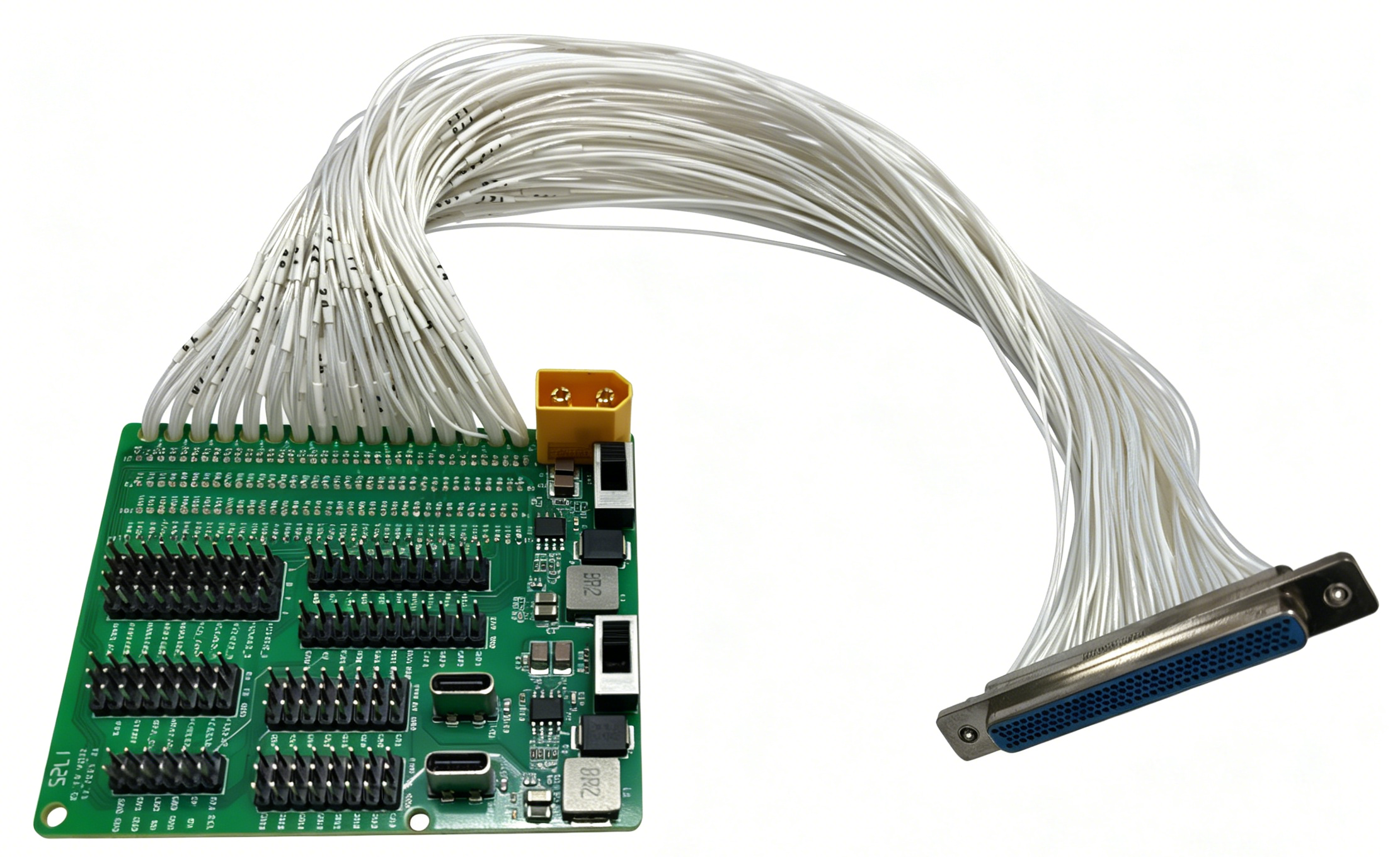
The debug cable shipped with the navigation flight control computer is shown below: