飞行模式配置
This topic explains how to map flight modes and other functions to the switches on your radio control transmitter.
:::tip In order to set up flight modes you must already have:
- Configured your radio
- Setup your transmitter to encode the physical positions of your mode switch(es) into a single channel. We provide examples for the popular Taranis transmitter below (check your documentation if you use a different transmitter).
:::
What Flight Modes and Switches Should I Set?
Flight Modes provide different types of autopilot-assisted flight, and fully autonomous flight. You can set any (or none) of the flight modes available to your vehicle.
Most users should set the following modes and functions, as these make the vehicle easier and safer to fly:
- Position mode — Easiest and safest mode for manual flight.
- Return mode — Return to launch position by safe path and land.
- (VTOL only) VTOL Transition Switch — Toggle between fixed-wing and multicopter flight configuration on VTOL vehicles.
It is also common to map switches to:
- Mission mode — This mode runs a pre-programmed mission sent by the ground control station.
- Kill Switch - Immediately stops all motor outputs (the vehicle will crash, which may in some circumstances be more desirable than allowing it to continue flying).
Flight Mode Selection
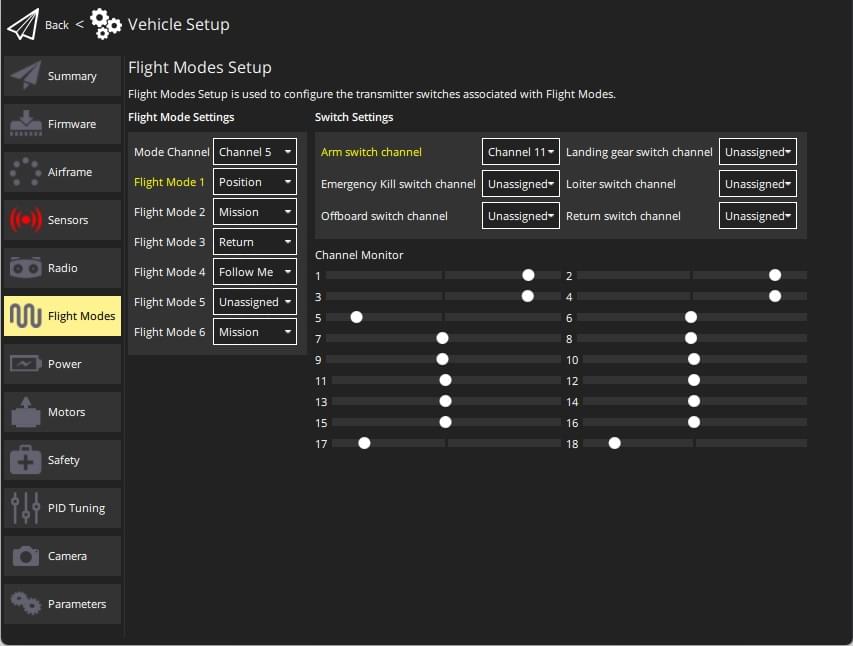
PX4 allows you to specify a "mode" channel and select up to 6 flight modes that will be activated based on the PWM value of the channel. You can also separately specify channels for mapping a kill switch, return to launch mode, and offboard mode.
To configure single-channel flight mode selection:
- Start QGroundControl and connect the vehicle.
- Turn on your RC transmitter.
- Select "Q" icon > Vehicle Setup > Flight Modes (sidebar) to open Flight Modes Setup.

- Specify Flight Mode Settings:
- Select the Mode channel (above this shown as Channel 5, but this will depend on your transmitter configuration).
- Move the transmitter switch (or switches) that you have set up for mode selection through the available positions. The mode slot matching your current switch position will be highlighted (above this is Flight Mode 1). ::: info While you can set flight modes in any of the 6 slots, only the channels that are mapped to switch positions will be highlighted/used. :::
- Select the flight mode that you want triggered for each switch position.
- Specify Switch Settings:
-
Select the channels that you want to map to specific actions - e.g.: Return mode, Kill switch, offboard mode, etc. (if you have spare switches and channels on your transmitter).
-
Test that the modes are mapped to the right transmitter switches:
- Check the Channel Monitor to confirm that the expected channel is changed by each switch.
- Select each mode switch on your transmitter in turn, and check that the desired flight mode is activated (the text turns yellow on QGroundControl for the active mode).
All values are automatically saved as they are changed.
RC Transmitter Setup
This section contains a small number of possible setup configurations for taranis. QGroundControl may have setup information for other transmitters here.
Taranis Setup: 3-way Switch Configuration for Single-Channel Mode
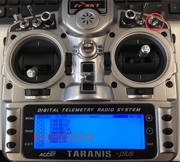
If you only need to support selecting between two or three modes then you can map the modes to the positions of a single 3-way switch. Below we show how to map the Taranis 3-way "SD" switch to channel 5.
::: info This example shows how to set up the popular FrSky Taranis transmitter. Transmitter setup will be different on other transmitters. :::
Open the Taranis UI MIXER page and scroll down to CH5, as shown below:

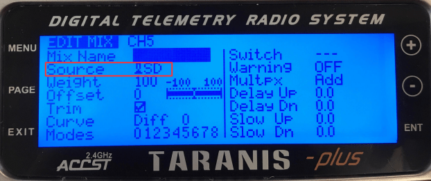
Press ENT(ER) to edit the CH5 configuration then change the Source to be the SD button.

That's it! Channel 5 will now output 3 different PWM values for the three different SD switch positions.
The QGroundControl configuration is then as described in the previous section.
Taranis Setup: Multi-Switch Configuration for Single-Channel Mode
Most transmitters do not have 6-way switches, so if you need to be able to support more modes than the number of switch positions available (up to 6) then you will have to represent them using multiple switches. Commonly this is done by encoding the positions of a 2- and a 3-position switch into a single channel, so that each switch position results in a different PWM value.
On the FrSky Taranis this process involves assigning a "logical switch" to each combination of positions of the two real switches. Each logical switch is then assigned to a different PWM value on the same channel.
The video below shows how this is done with the FrSky Taranis transmitter.
The QGroundControl configuration is then as described above.
Further Information
- Flight Modes Overview
- QGroundControl > Flight Modes
- PX4 Setup Video - @6m53s (Youtube)
- Radio switch parameters - Can be used to set mappings via parameters